

Three Identical Brackets on the Review Table
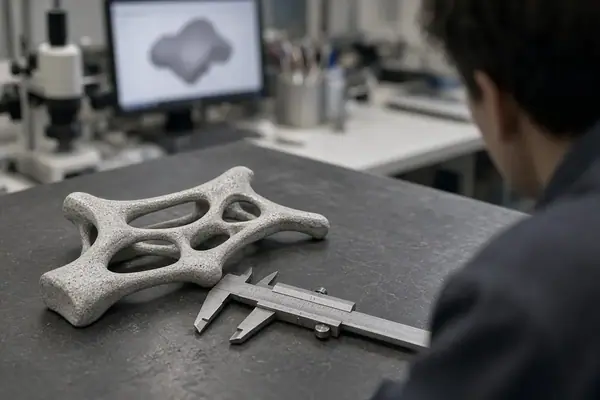
Three physical prints of a clevis-mounted bracket sit side by side at a late structural review. Each came from a separate generative run. Their outer envelopes match.
The logs look orderly: mass eases down, and existing webs thicken where the original sketch already placed them. Yet no new load path appears. The team proposes changing the optimizer’s step-size settings. The lead analyst stops the queue and opens the parameter mapping file instead.
That is the consequential move. The variable list never included a feature that could appear, move, or vanish. The search had permission to resize familiar geometry, so familiar geometry returned.
Before I would approve another run, I would ask a more basic question: can this encoding express a different load path at all?
What the Encoding Fixes Before the First Iteration
Design-space encoding combines the variables, their bounds, the constraints, and the representation that maps variable values onto a solid. Together, these choices define the admissible set: the designs the optimization problem permits.
An objective can rank candidates within that set. It cannot discover a geometric change that the mapping cannot express. Multi-objective optimization inherits the same boundary; adding another objective does not add missing geometric freedom.
For the bracket, separate the setup into four levers:
- Variables: flange inclination can change only if the variable vector includes it and the geometry mapping responds to it.
- Bounds: wall-thickness limits restrict the available dimensions to the intended process envelope.
- Constraints: stress limits and support conditions define acceptable mechanical behavior around the bearing lugs and mounting interfaces.
- Representation: a CAD parameter vector, voxel density field, boundary level set, or member graph determines how a candidate becomes geometry.
This framework addresses linear-elastic structural components. Buckling, heat transfer, and fluid-flow problems require their own variable mappings and physical constraints. Even within structural engineering applications, an admissible design remains a claim to verify on the realized solid.
How a Representation Scheme Biases the Geometry
A parametric CAD model gives the search an explicit geometric vocabulary. With fixed topology, it can resize existing ribs and fillets while preserving familiar interfaces. That control helps downstream CAD work, but a hole pattern, split load path, or removed wall requires an expressible operation in the model.
A density field broadens the reachable topology. Material can redistribute throughout the design domain rather than follow the feature tree. The trade-off moves into discretization and regularization: element size, filtering, and thresholding influence which members survive reconstruction. A sensitivity filter alone should not be treated as a guaranteed minimum-thickness constraint.

Level-set methods move an interface through the domain. Their reach depends on the initial interface and the evolution formulation. Boundary advection without a mechanism for hole nucleation cannot simply create an internal void in an initially solid region. Seeding voids or adding a nucleation mechanism expands that reach, while introducing further initialization or formulation choices.
A member graph has its own restriction: a load path between absent node pairs remains unrepresentable. Each scheme carries a geometric prior. Which prior has the review actually accepted?
Infeasible Candidates That Start in the Variable Bounds
A queue full of rejected candidates deserves an encoding audit before a penalty-weight adjustment.
In the bracket investigation, the engineers decoded an intermediate density field into a watertight boundary representation and checked the realized solid. That check exposed a mismatch between the stress constraint evaluated on smeared density and the notch stress in the explicit geometry. The optimizer had been answering the problem it received; the exported part exposed the gap.
Bounds can create a similar mismatch. Overly restrictive limits may exclude a workable process geometry. Excessively permissive limits admit walls, draft conditions, or cutter approaches that the intended process cannot produce. The first export then becomes a rejection gate rather than a useful design candidate.
Check the Decoded Bracket
Decode a candidate and evaluate the quantities the review will accept: actual wall thickness, accessible surfaces, and stress on the realized solid.
Also inspect the constraint mapping. A volume limit needs a reliable relationship to realized volume. A support coordinate needs a meaningful connection to the modeled interface. A stress constraint needs a defined evaluation geometry. Without those connections, solver convergence says little about an acceptable bracket.
One Load Path, Two Encodings, Different Reachable Parts
Hold the bracket loads, mounting interfaces, and mass intent constant. Change only the encoding. This comparison tests geometric reach rather than optimizer speed.
Encoding A uses a short CAD dimension table on frozen topology. Existing rib thicknesses and fillet radii can change. A diagonal member absent from the feature structure cannot emerge. Repeated runs retain the outer envelope because the available family preserves it.
Encoding B uses a continuous field with protected bolt-boss regions, process-related length scales, and support rules. It can admit a diagonal tension member or remove a redundant web, provided the decoded geometry satisfies the acceptance checks.
The broader representation also creates more reconstruction work. Threshold selection, boundary cleanup, and verification become part of the CAD-to-CAE handoff. That cost belongs in the comparison.
I would put the review’s acceptable changes beside both mappings: can each create a diagonal web, delete an existing rib, and preserve the mounting interfaces? Those answers establish whether the search can reach a meaningfully different bracket.
Encode the Physics You Will Accept, Not the Shape You Already Like
The next run needs a written geometric permission list before it needs revised solver settings. Make that list concrete: a diagonal tension web may appear; a redundant rib may disappear; mounting interfaces must remain usable.
Then check the encoding against those permissions:
- Remove frozen sketch dependencies that prevent accepted load-path changes.
- Tie variable bounds to the intended manufacturing envelope.
- Evaluate acceptance constraints on the decoded geometry.
- Require the representation to create or delete the features the review permits.
Freeze the admissible physics and process limits, then leave geometry free inside that set. Treat a repeated envelope as an encoding result until the admissible set demonstrably contains a different part. Reject any representation that cannot express an approved load-path change before allocating the next solver run.





Comments
Nothing here yet. Add your opinion.
Add Your Thoughts