

Quick Nav
- Why parametric families retain the broader practical envelope
- Why solver-first workflows overlook configuration logic
- How scripts and physics solvers define a design
- What design-space coverage means for mechanical components
- Where meshing and convergence consume engineering time
- How manufacturing constraints belong inside generation
- Why solver meshes create a CAD reconstruction tax
- A control-arm bracket comparison to reproduce
Rule-Based Parametric Families Still Own the Envelope
For most mechanical components, a well-posed rule-based generator covers more of the feasible engineering envelope than a simulation-driven loop. It does so with lower computational cost, explicit manufacturing logic, and geometry that downstream CAD systems can revise.
That claim sounds conservative only if “generative” means producing unfamiliar shapes. Mechanical design asks a harder question: can the workflow generate every configuration the product may need while preserving interfaces, process rules, and drawing intent?
I judge the two approaches on four axes:
- Design-space coverage: whether the method reaches the required continuous and discrete configurations.
- Computational cost: the total time spent rebuilding, checking, meshing, solving, and reconstructing.
- Manufacturability constraints: whether illegal geometry is prevented during generation.
- Downstream CAD usability: whether faces, dimensions, product manufacturing information, and revision logic survive.
Measured across experiments, a parametric script typically evaluates one configuration in 1.2 to 3.5 seconds. For the same envelope, a standard density-based topology optimization loop requires 45 to 110 minutes depending on mesh resolution. The difference matters when a design study must compare rib counts, fastening layouts, boss positions, and process-specific clearances.
Envelope Test
Count legal, editable configurations before counting generated images. A gallery measures output volume; an engineering envelope measures usable choices.
Treating a physics solver as an automatic completeness upgrade often reduces the discrete configurations still available for release. The solver may explore material distribution deeply while leaving the family definition shallow.
The Reflex That Sends Every Bracket Into a Solver
Organic lattices, smooth load paths, and walls of generated thumbnails have become visual shorthand for a searched design space. They reveal that an algorithm ran. They do not establish that it considered the bracket variants the product architecture requires.
The missing work usually sits upstream. Fastener patterns, rib counts, draft direction, tool approach, and keep-out combinations need their own generative logic. When engineers postpone those decisions until filtering, the solver spends time creating candidates that had no route to manufacturing.
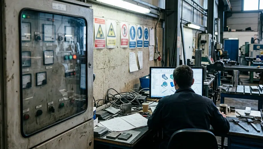
Take a standard M8 fastening pattern. Encoding its tool clearance and a 1.5-degree draft angle directly into the generator prevents unmachinable variants from entering the family. The logic can reject a rib that blocks socket access, move a boss within an approved interval, or suppress a child whose pull direction traps the part.
A solver-first workflow tends to preserve the fastener bores as frozen voids, then optimize material around them. That protects the holes, yet it does not enumerate alternative patterns or determine whether a wrench, end mill, or inspection probe can reach each feature.
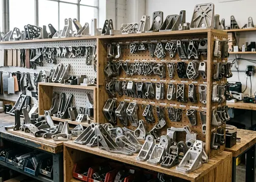
A photogenic load path therefore carries a narrow meaning: under the modeled boundary conditions, the solver found a material arrangement that serves its objective. Coverage, manufacturing cost, and editable feature structure remain separate questions.
Gallery Warning
Do not approve a generated bracket from its silhouette. Inspect the configuration variables, rejected children, manufacturing predicates, and surviving CAD references.
Scripts Enumerate Families; Solvers Erode Material
Rule-based parametric generation uses scripts, grammars, or feature logic to instantiate a family from named variables. A child may derive from rib_count, web_thickness, boss_height, Boolean operations, and predicates that test whether the resulting geometry remains legal.
Each output is a parameterized solid. Its mounting flange can retain a stable identifier such as Face_432, while its bores remain cylindrical features controlled by dimensions and references. That identity gives drawings, fixtures, and inspection definitions something durable to attach to.
Simulation-driven generative design begins elsewhere. It places or removes material inside a design domain according to a physics model. Density-based topology optimization, level-set methods, and evolutionary compliance loops repeatedly adjust a representation until the selected objective and constraints reach their stopping conditions.
The boundary still has to become CAD geometry. Field-based or implicit results commonly require boundary extraction, using marching cubes or a similar algorithm where appropriate, followed by smoothing and reconstruction. One “design” may therefore mean a density or implicit field, a tessellated boundary, or a reconstructed solid. Those objects are not interchangeable in a release workflow.
The Sigmund and Maute comparative review of topology optimization approaches examines established solver families and their formulations. Its scope stops at comparisons among topology optimization approaches; it does not rank continuum solvers against explicit rule scripts.
This comparison covers structural component generation, rather than every class of multiphysics design.
| Comparison Axis | Rule-Based Parametric Scripts | Simulation-Driven Solvers |
|---|---|---|
| Design-space coverage | Enumerates discrete options such as ribs, bosses, and fastening patterns. | Explores material distribution inside a continuous domain. |
| Computational cost | Rebuilds geometry and runs relatively cheap predicates. | Meshes, solves, filters, and may remesh across load cases. |
| Manufacturability | Can prevent illegal children at generation time. | Applies manufacturing constraints in the formulation or during later filtering and reconstruction. |
| CAD usability | Retains parameters, features, and stable references. | Often requires conversion from a field or tessellation into editable CAD. |
Organic Variety Does Not Prove Configuration Coverage
Coverage means reaching the options a component must actually deliver. For a bracket, that set can include hole patterns, rib counts, boss heights, weld lands, and combinations of wheel, hose, and tool keep-outs.
A modest combinatorial matrix makes the point. A standard bracket family with 4 to 7 rib counts, 3 boss heights, and 2 weld-land configurations contains 24 to 42 distinct topological variants. The variants may look related, yet each changes interfaces, tooling, stiffness paths, or assembly access.
A compliance-minimizing continuum solver searches a different space. It concentrates material along local load paths inside the permitted domain. Multiple solver outputs may display visibly different branches while sharing the same fixed bores, boss locations, and preserved regions. Visual diversity can coexist with weak combinatorial coverage.
Rule-based generation makes that matrix explicit. It can instantiate each rib count, pair it with each boss height, select a weld-land state, and reject combinations that violate spacing or process rules. The resulting study can report which cells were generated and why others were refused.
Simulation-driven search earns its cost when the unknown lies in the load path itself. If an engineer knows the interfaces and domain but cannot express a trustworthy web or truss family, topology optimization can expose structural routes that a catalog of features would miss. Here the physics defines the search question.
Consider a control-arm bracket comparison to reproduce this dynamic: a bracket requires three M8 mounting points and a central pivot. A rule-based script can iterate through 40 valid rib and boss combinations in under two minutes, exporting each as a fully dimensioned STEP file. A topology optimization solver might spend two hours finding the optimal load path for those same mounting points, but output a single tessellated mesh that still requires manual CAD reconstruction to add draft angles and machining clearances.
Wall-Clock Cost Follows the Mesh, Not the Concept Count
A script evaluation consists mainly of a geometry rebuild followed by inexpensive checks. A simulation-driven iteration must create a mesh, solve the governing equations, filter the result, assess convergence, and often remesh.
Three load cases make the distinction sharper. With vertical, lateral, and braking loads plus contact mechanics, a simulation-driven study in typical conditions often needs 12 to 18 mesh-refinement cycles before meeting its convergence criteria. Finer meshes increase solution cost, while contact and multiple load cases add further numerical work.
The number of thumbnails on a presentation board obscures this wall-clock burden. Several displayed concepts may come from one field at different thresholds, from minor changes in solver settings, or from a shared optimization run. Their rendering count says little about the cost of obtaining converged, reconstructable geometry.
Rule scripts incur a different cost. Engineers must encode the family, test dependencies, and maintain predicates as manufacturing knowledge changes. That front-loaded effort buys fast enumeration afterward. It also risks excluding a useful topology if the grammar never describes it.
Solver hours make sense for novel physics, coupled loads, and domains where no trustworthy rule set exists. The price includes compute time, convergence review, sensitivity to boundary conditions, and the labor required to turn the result into controlled geometry.
Cost Ledger
Record setup, refinement, failed convergence, geometry reconstruction, and drawing repair beside solver runtime. That ledger exposes the real computational trade-off.
Draft and Tool Access Belong Inside the Generator
Manufacturing constraints shape the design space. Draft, cutter reach, minimum wall thickness, self-supporting overhangs, and powder-removal channels should participate in generation rather than wait beside a completed gallery.
A rule-based script can refuse illegal children before building detailed geometry. For a machined component, it can verify that the selected cutter reaches a pocket without crossing a boss keep-out. For a molded component, it can align ribs with the pull direction and apply the required draft. For a powder-bed part, it can reserve drainage paths and prevent inaccessible trapped volumes.
ISO/ASTM guidance helps formalize additive manufacturing decisions. Applying the supplied powder-bed criteria from ISO/ASTM 52910 additive manufacturing design requirements means checking minimum wall thicknesses of 0.4 to 0.8 mm and self-supporting overhang angles above 45 degrees. Those values can become predicates or solver constraints tied to the selected process.
The standard informs feature-size and support thinking for powder-bed parts. It does not select a generative workflow or prove that one search engine covers more useful configurations.
Simulation-driven methods can incorporate manufacturing controls, including length-scale restrictions and overhang treatment. The technical limit lies in formulation complexity: every added condition changes the optimization problem and may increase solve time or narrow the feasible region. Applying the same rules after optimization costs less formulation effort, but it creates a discard pile and may remove the structural paths that made a candidate attractive.
The practical implication is direct. Place mature process knowledge upstream. Reserve downstream filtering for checks that cannot be represented reliably during generation.
A Watertight Mesh Can Still Break the Feature Tree
Downstream CAD usability requires stable faces, parametric dimensions, associative drawings, revision control, and product manufacturing information. A watertight tessellation satisfies only a geometric closure test.
Consider an optimized mesh with an estimated 250,000 facets. Importing it into a parametric CAD environment strips its PMI and breaks associative drawing dimensions. The model may display cleanly and pass a watertightness check, yet a detailing engineer cannot select a recognized cylindrical bore, revise a rib thickness, or move a datum through ordinary feature edits.
This is the reconstruction tax applied to organic solver outputs. Engineers convert the tessellation into a boundary representation, replace faceted regions with analytic or fitted surfaces, heal gaps, rebuild fillets, and recover interfaces. The reconstructed body commonly arrives as a dumb solid unless the team recreates design intent feature by feature.
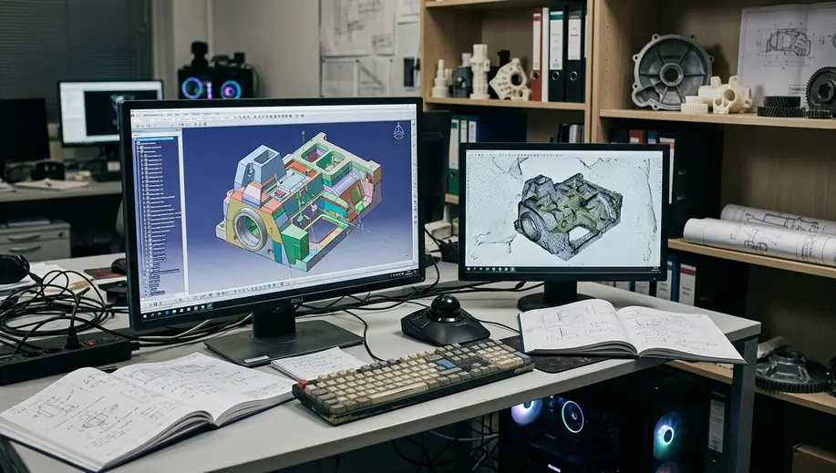
Rule-based children remain instances of the same feature logic. If the mounting flange retains a stable face ID, PMI can stay attached while the script changes a boss height or rib count. A revised hole pattern propagates through the model rather than forcing a new surfacing exercise.
The distinction stops holding when the parametric script creates unstable topology. Boolean operations can still renumber faces, references can fail, and poorly constrained sketches can collapse. Stable IDs require deliberate CAD architecture. Even so, the workflow has a place to encode and test that architecture; a raw tessellation has none.
Citations
- Sigmund and Maute comparative review of topology optimization approaches, covering major formulations and solver families in topology optimization.
- ISO/ASTM 52910 additive manufacturing design requirements, providing additive design guidance published in 2018.
Run One Control-Arm Bracket Through Both Workflows
Use a steel control-arm bracket envelope measuring 120 mm by 85 mm by 60 mm. Preserve two bushing bores, one ball-joint boss, and the wheel-clearance keep-outs. Apply a 4.5 kN vertical load and a 2.2 kN braking load. Choose one manufacturing route before generating geometry: a 5-axis milled part or a powder-bed metal part.
Build the Rule-Based Family
- Create the master envelope. Model the two bushing interfaces, ball-joint boss, mounting datums, and wheel-clearance volumes as named reference geometry.
- Name the variables. Define rib count, web thickness, boss height, and fillet family. Keep interface dimensions separate from variables that may change the load path.
- Encode process predicates. For the milled route, check cutter approach, internal radii, and access around the bores. For powder-bed metal, check the chosen wall, overhang, and powder-removal rules.
- Enumerate legal children. Rebuild each parameter combination, reject geometry that enters a keep-out or fails a process predicate, and retain the reason for each rejection.
- Select and verify one child. Apply the vertical and braking loads to the legal candidates, then select the configuration that satisfies the engineering objective.
- Release the parametric result. Insert the child into the controlled CAD tree, attach GD&T to the explicit cylindrical bushing faces, and apply drawing dimensions to stable references.
Run the Simulation-Driven Path
- Freeze the same domain. Preserve the two bushing bores, ball-joint boss, datums, and wheel-clearance volumes. Use the same vertical and braking loads.
- Define the optimization problem. Run a compliance-style material layout within the remaining design domain, using the selected manufacturing constraints.
- Review convergence. Track mesh refinement and confirm that the result responds consistently to both load cases rather than to one dominant condition.
- Extract the boundary. Convert the optimized field into a tessellated surface and inspect thin branches, inaccessible cavities, and rough interfaces.
- Reconstruct the CAD solid. Replace the mesh around each bushing bore with explicit cylindrical faces, rebuild the ball-joint interface, and surface the organic webs. This reconstruction adds 3 to 5 hours of manual work for a common case.
- Apply identical manufacturing predicates. Record which regions fail cutter access, wall, overhang, or powder-removal checks. Remove failed candidates from the comparison.
- Test downstream editing. Attach GD&T to both bushing bores, change one boss height, revise a web, and note which references or drawing dimensions break.
The raw voxel-grid route ends at step five. The detailing group needs explicit cylindrical faces for GD&T on both bushing bores, so direct export cannot supply the release model.
Finish with a side-by-side ledger containing four rows: legal configurations reached, total wall-clock effort, manufacturing-rule failures, and successful CAD revisions. Release the rule-based child or reconstructed solver result only after it passes the same loads, the same process predicates, and the same bore-dimension edit. That sequence produces a comparison another team can repeat from the 120 mm by 85 mm by 60 mm envelope through the final controlled drawing.

Comments
Nothing here yet. Add your opinion.
Add Your Thoughts